Assembly and Tree Installation
This Guide Installation Guide is intended to explain how to successfully install a Rainforest Connection Guardian Device in project setting. Please read this guide at least once through before entering the field and climbing a tree.
Once in the field you can then have this guide on your phone and refer to it during the installation process.
- Completed the Pre-installation Setup
- Completed the Climber Checklist Cellular [pdf] or Satellite [pdf]
- Project owner has completed the Location Selection
Step 1: Tree selection
On arrival at the selected location, select a tree for the Guardian which has gaps in the canopy and light canopy cover.
The tree must be:
- alive
- emergent (above average canopy of surrounding forest)
- distant from distracting noises (e.g. not near fast flowing rivers or busy roads) The distant will depend on the density of forest, but ideally at least 1km from busy roads and 500m from large fast flowing rivers.

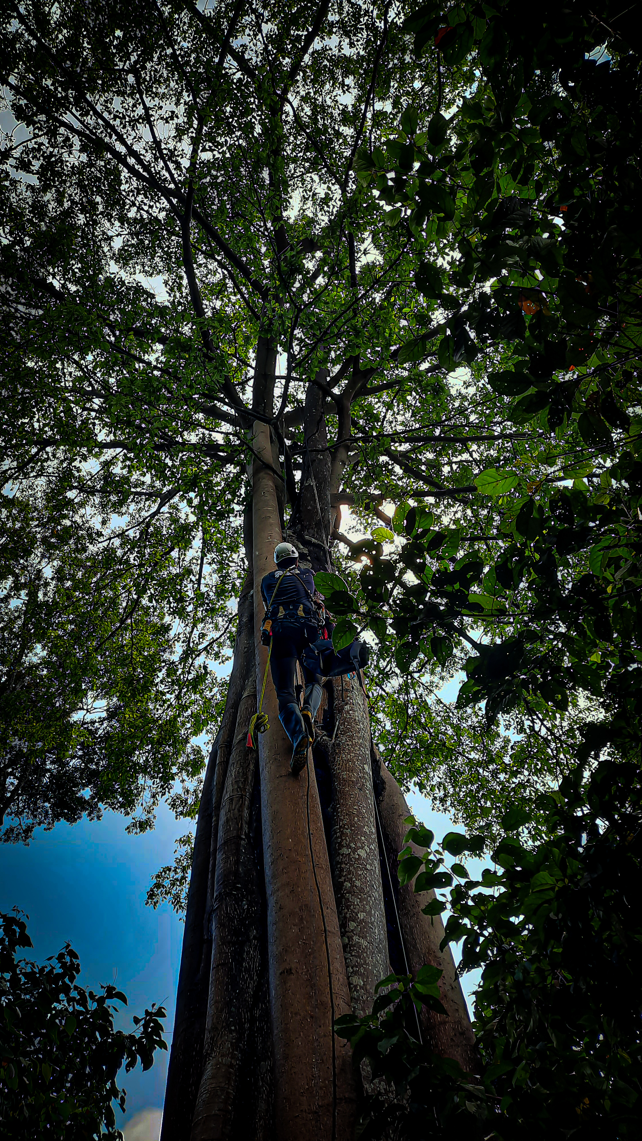
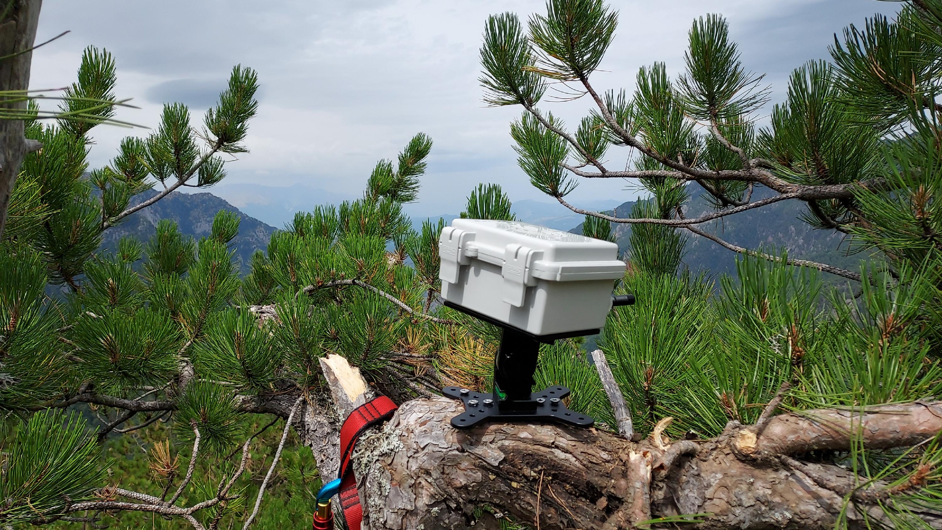
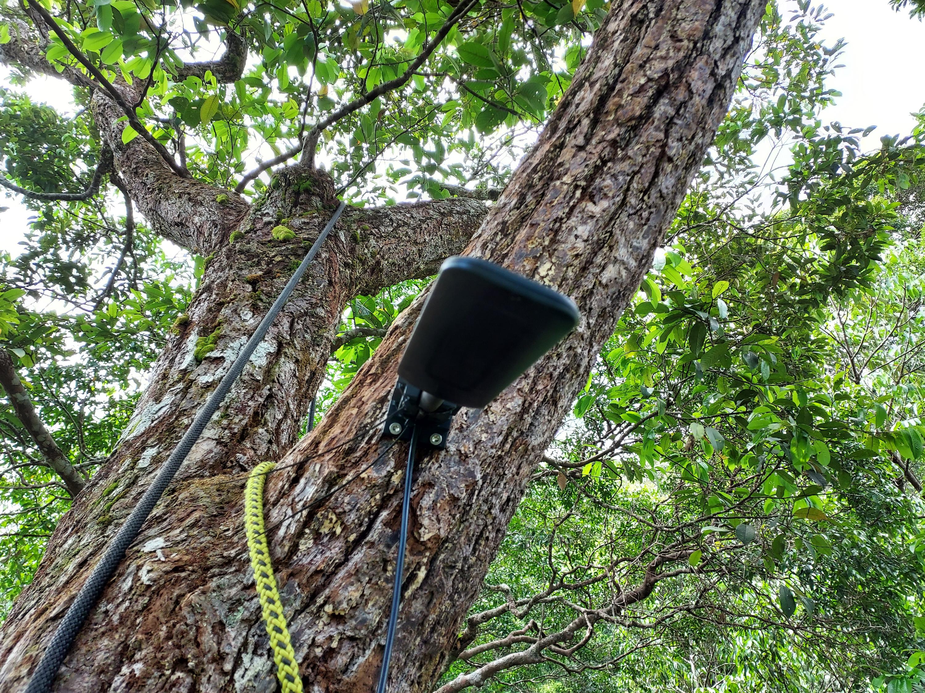
Figure 1: Suitable tree
Figure 1 depicts a tree which is appropriate for a Guardian because it emerges above the surrounding canopy and has gaps in its canopy necessary to maximise the sunlight on the solar panels. Moreover, it also has some horizontal branches at the top which can facilitate direct baseplate to Guardian installation (see step 3).

Figure 2: Unsuitable tree
Figure 2 shows a less appropriate tree because it clearly isn't emerging above the surrounding forest canopy. Moreover, it also has very full canopy cover, meaning the Guardian's access to solar power will be restricted. Putting a Guardian in this tree would be difficult because in order to create a canopy gap for sunlight and the satellite antenna the climber would have to reach the very top of the tree where the branches would be quite small and potentially unable to support a Guardian.
If you are installing a satellite device then you will also need to find a position for the satellite antenna 1-2 metres away from the Guardian with canopy coverage of no more than 80%.
Step 2: Preparing (equipment) to climb
Important: Assembly of the device must be done in the tree. Do NOT assemble on the ground as it could result in damage to the device while climbing.
*it is possible to assemble ONLY the Swarm Antenna on the ground and carry it up, however, climbing with the swarm antenna must be done carefully*
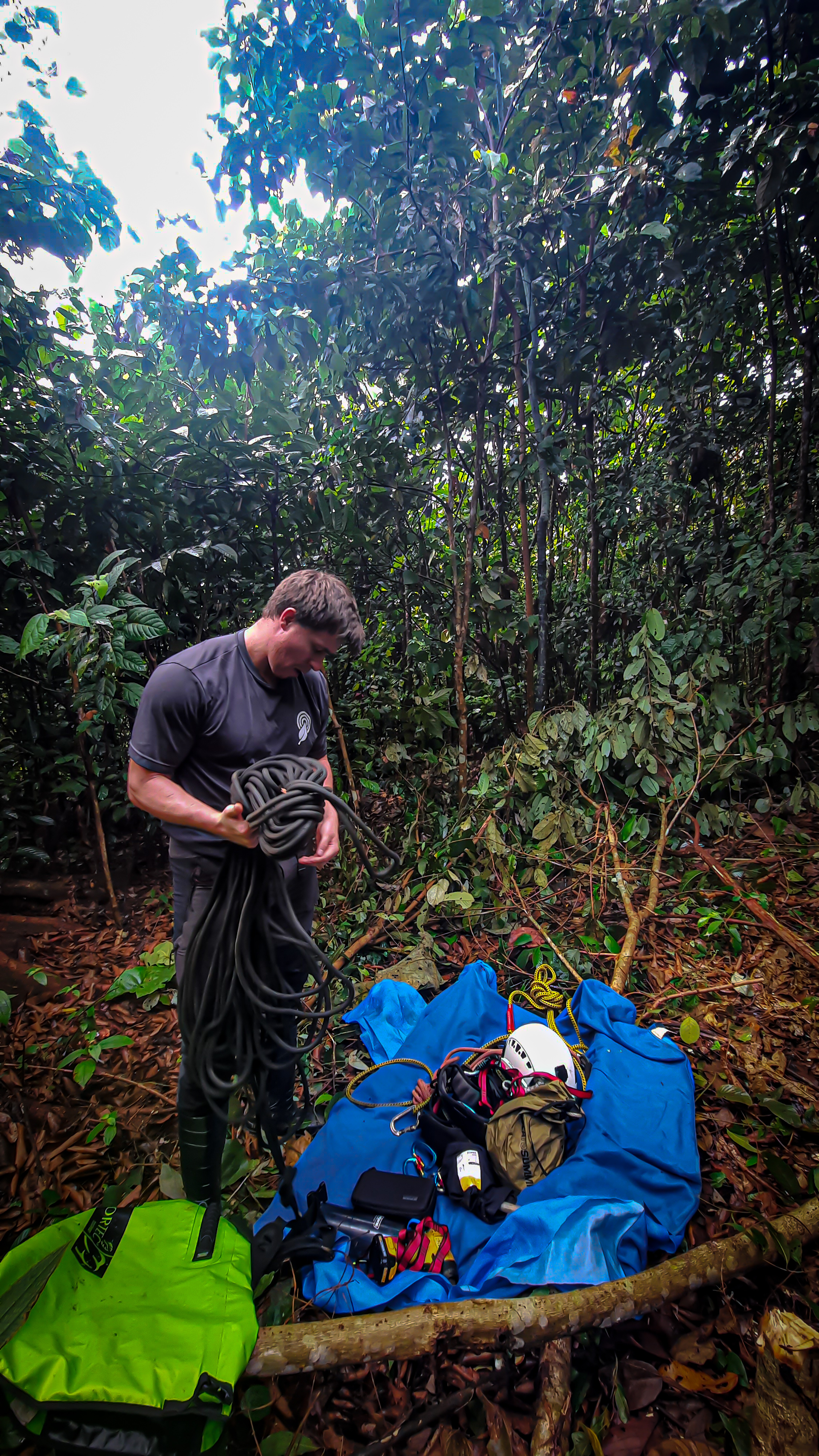
Place all the Guardian and climbing equipment on a ground mat to ensure no equipment can be lost. (please make sure you have check all your climbing equipment and Guardian equipment the night before).
Set the tree for climbing using your technique of climbing: fire the line, pull ropes over, etc.
You will need to take the Guardian set (inside RFCx bag), impact driver, Android phone with Companion App, cable ties, a hand saw and pliers into the tree for installation. A 20mm spanner and a 6m Allen key are also needed for satellite antenna assembly in the tree. A GoPro is also useful for documenting the install.
All items you carry into the tree must be attached to your harness via straps / carabiners and should remain so until you reach the installation height in the tree.

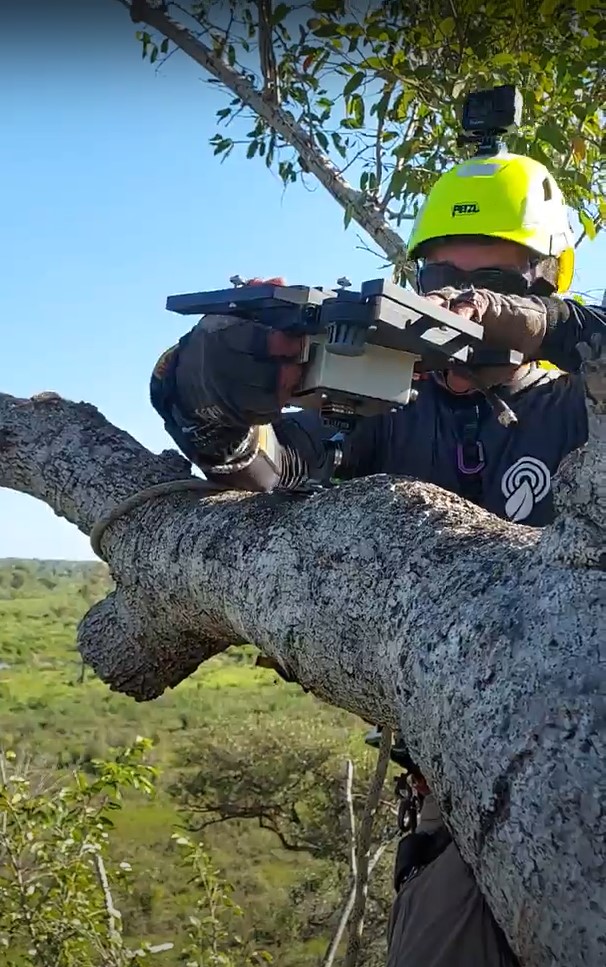
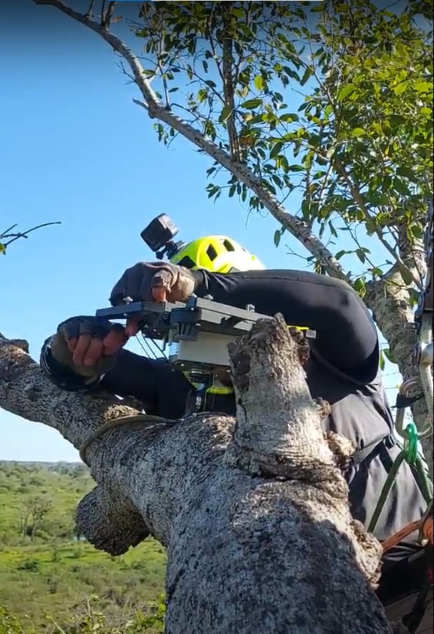
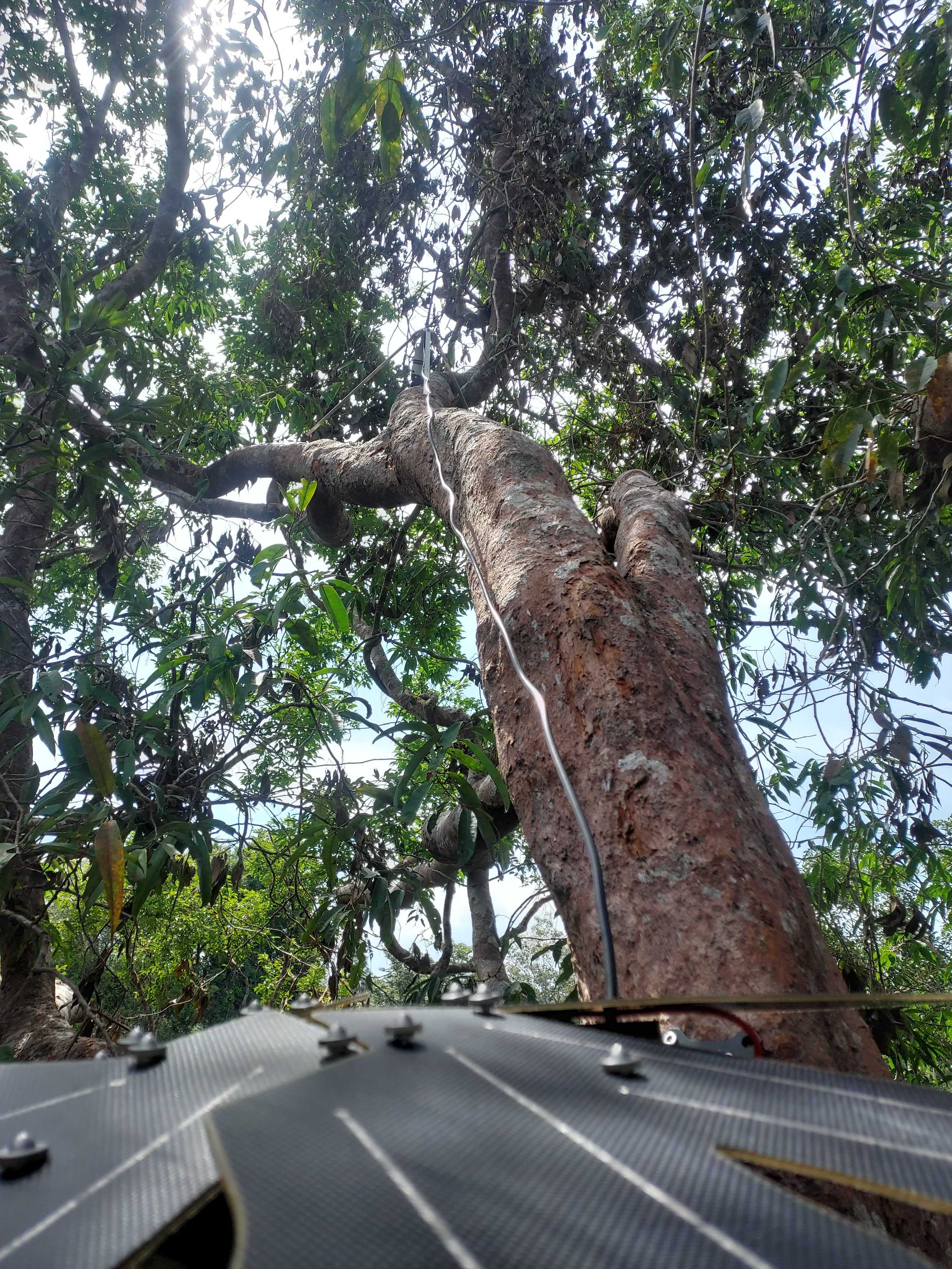
Once you have climbed the tree to the height where you will install the Guardian it may be important to prune branches that are blocking sunlight access to the Guardian’s solar panels and create a surface to attach the GSM or Satellite antennas securely and so they are pointing directly up. This is a vital step in ensuring that Guardians have longevity as they will be able to charge effectively and consistently. Do this before you install any parts of the Guardian to ensure branches do not fall on the Guardian and damage it.
NB. You will need to access the highest point in the tree that is safely accessible. This will Optimise access to sunlight, satellite signal and GSM signal.
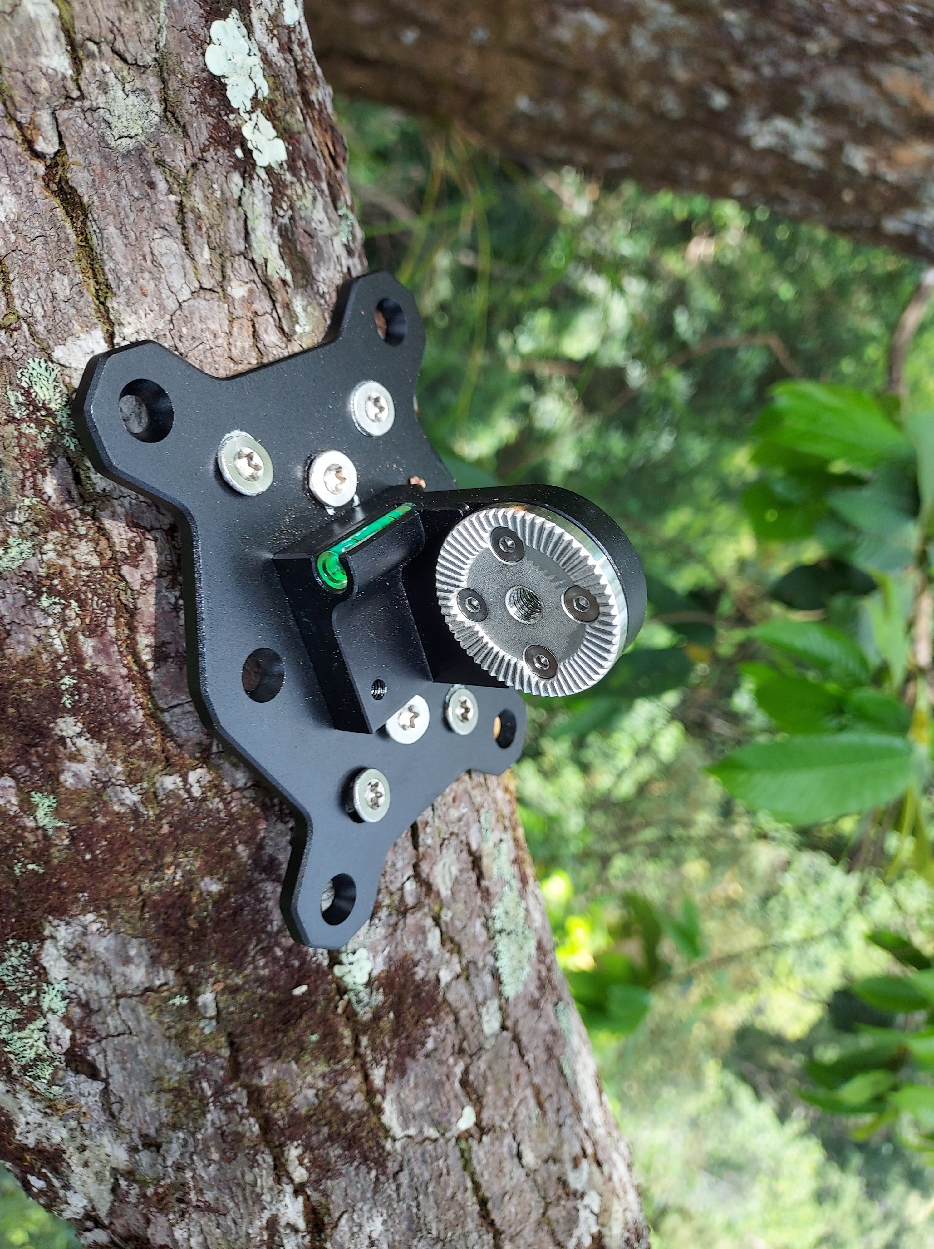
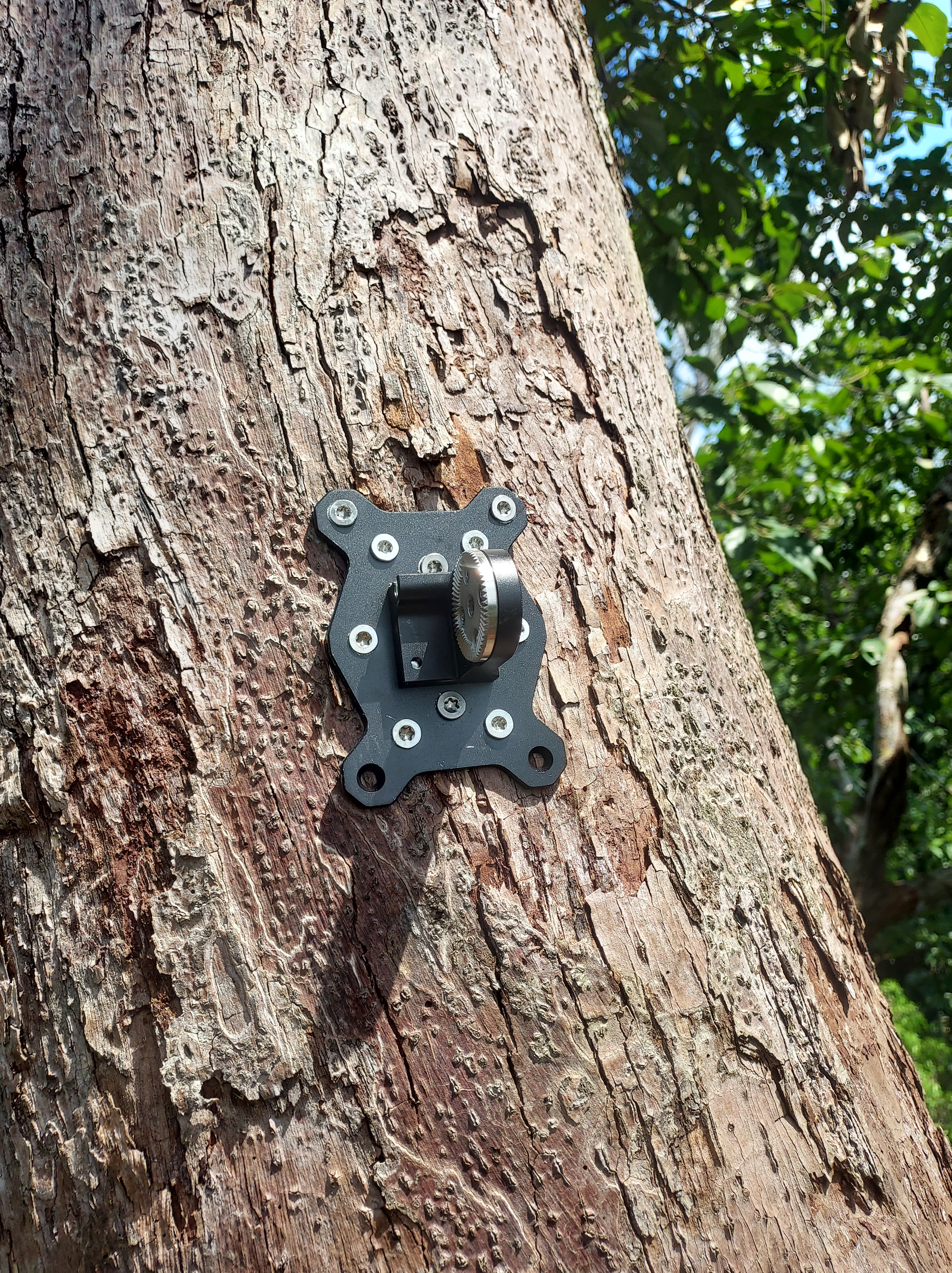
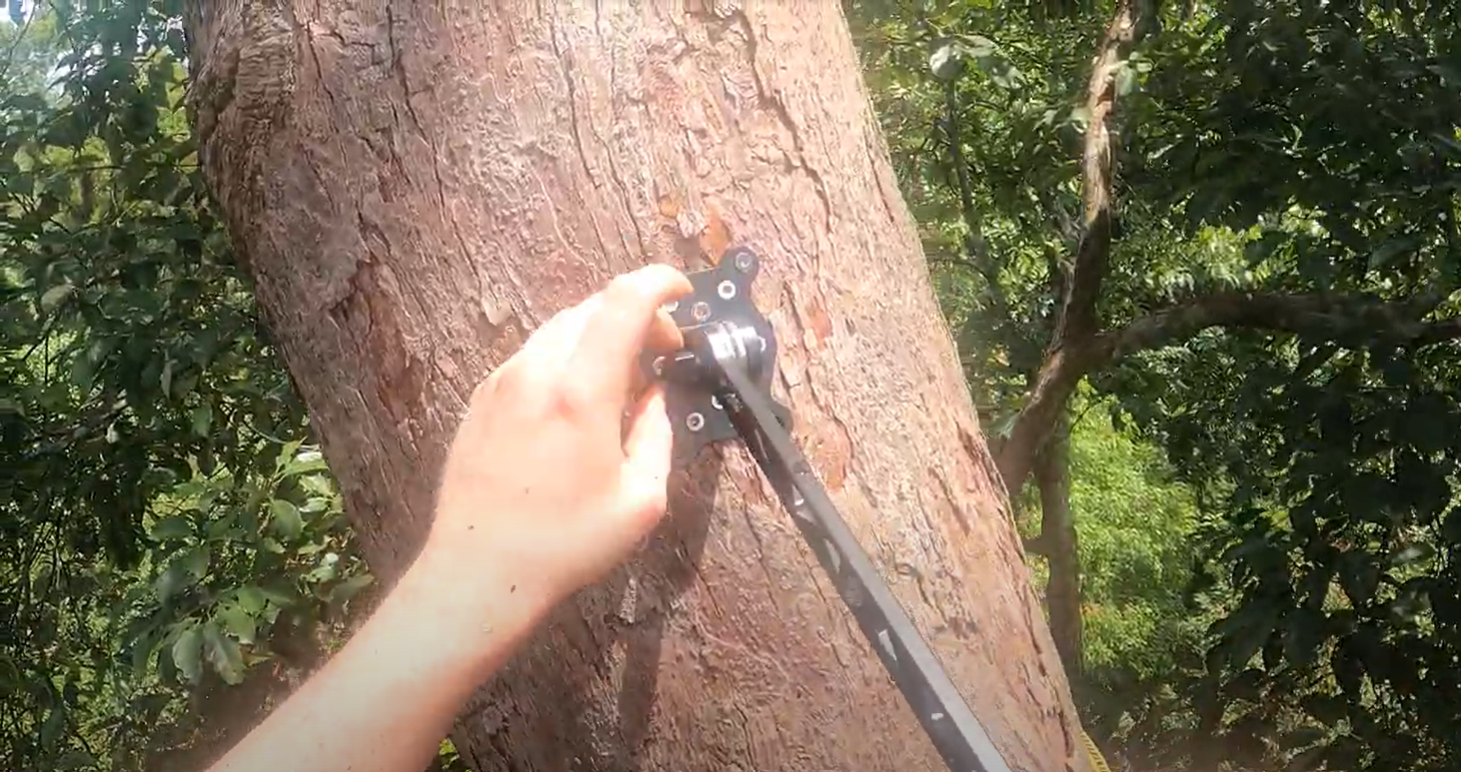
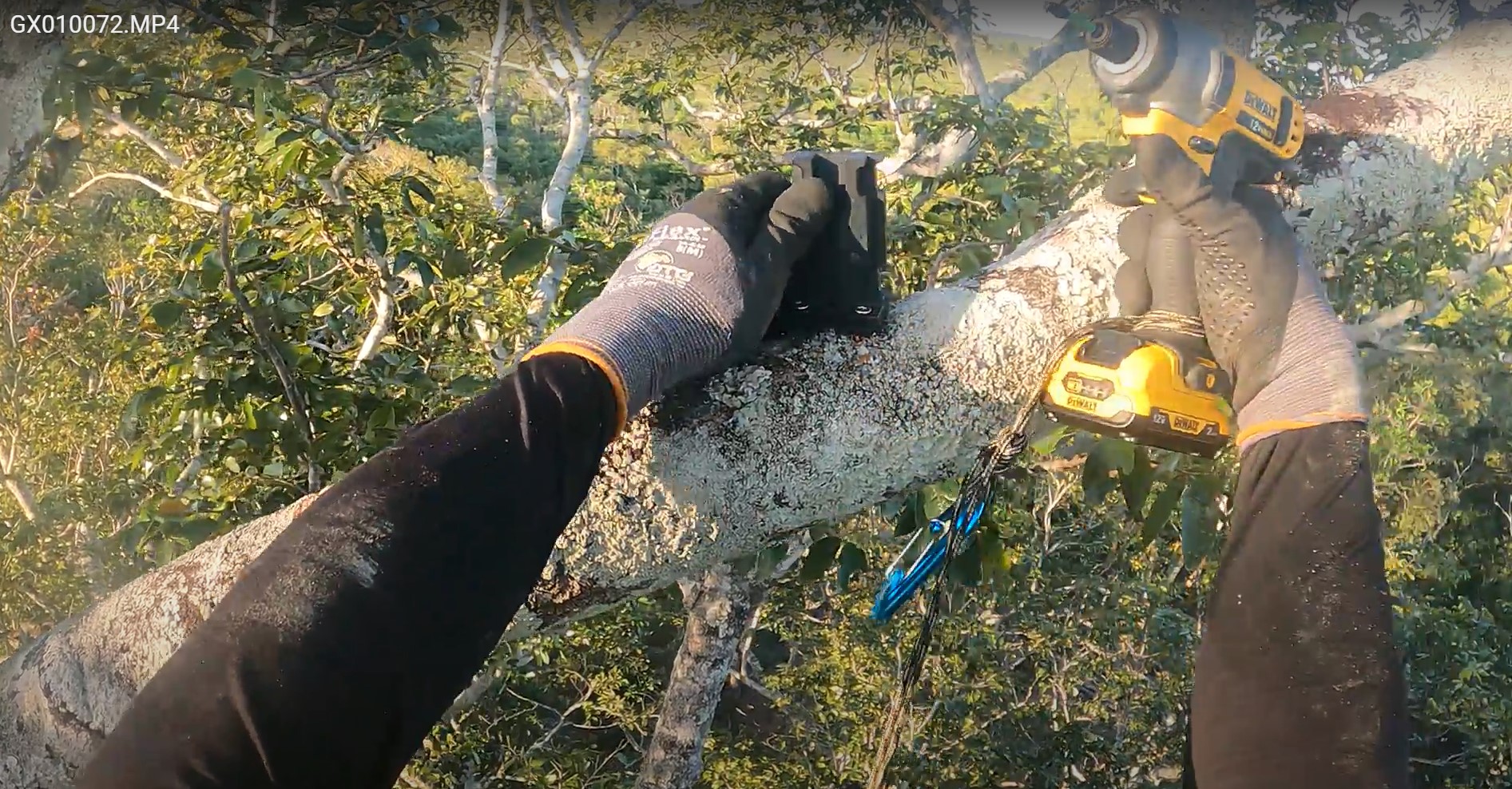
Step 3: Baseplate attachment to the tree
The Baseplate is the 12 hole metal plate with a spirit level which is secured to the tree with the provided stainless steel screws. You must bring your own impact driver/drill. The appropriate drill bit will be supplied.
There are two main positions the Baseplate can be installed. The first (most desirable) is to attach the Baseplate on a horizontal branch (see Figure 6). The second is on the trunk (or vertical branch) which requires the Arm attachment as described below.
Choose a position for the Baseplate that maximizes the tightness against the branch or trunk. The baseplate should be secured by at least 10 screws (preferably all). Minimize the gaps between the Baseplate and the tree to ensure vibrations don't loosen the Baseplate over time.
If you have attached the Baseplate to a vertical then you can use the Arm to give clearance to the solar panels (which must face upwards). Note: if you attached the Baseplate to a horizontal then you should not need to use the Arm. The Arm comes with a rosette hinge joint which will fit against the rosette joint on the Baseplate. Place the arm against the Baseplate joint and tighten with the your fingers as tightly as possible.
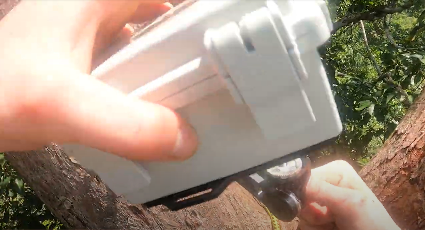
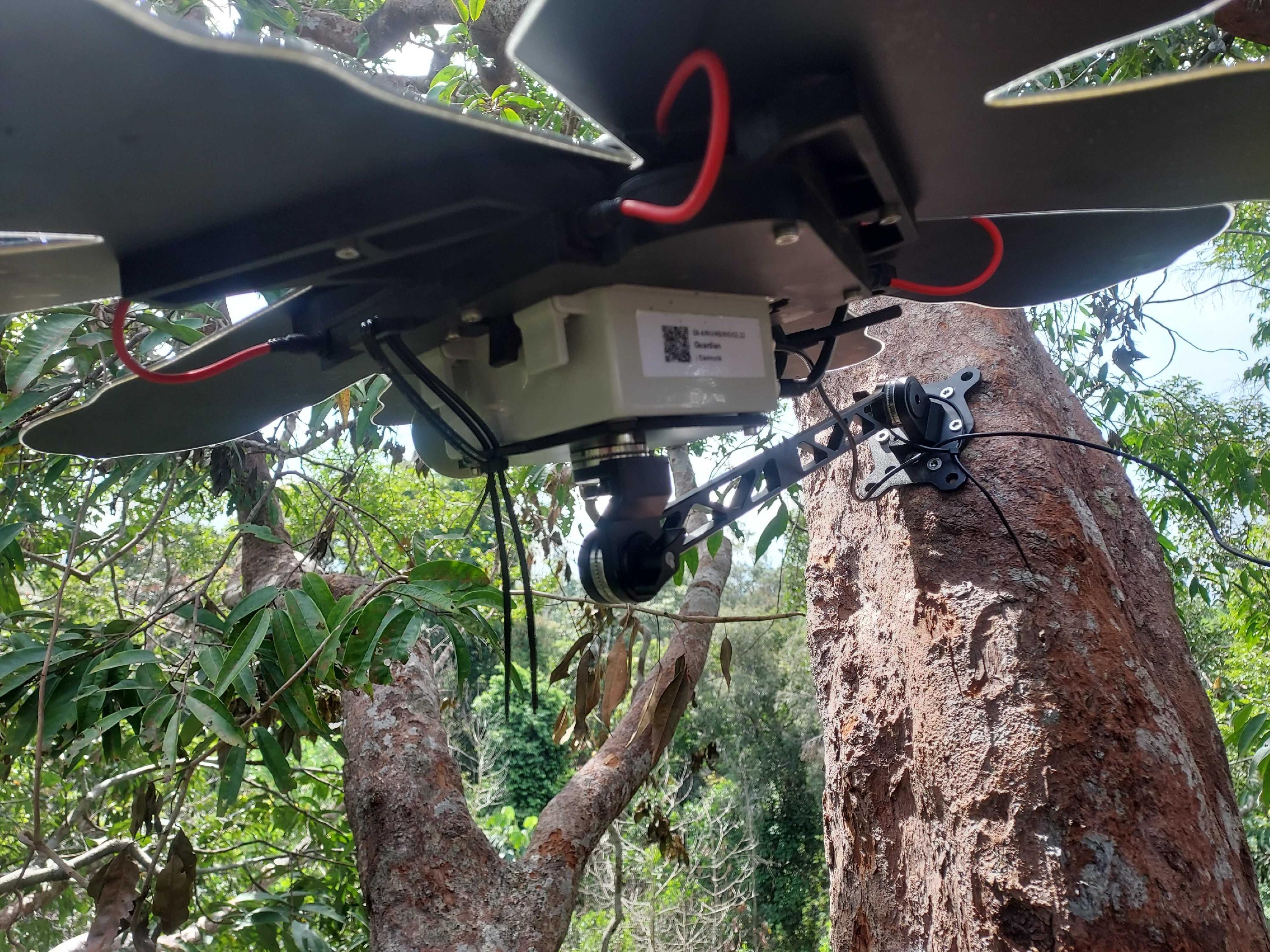
Step 4: Attaching Box to Baseplate or Arm
The Box has a rosette joint on the bottom to directly attach it to the Baseplate or to attach it to the Arm. Position the Box so that the logo is facing upwards in one of the configurations shown in Figure 9. The bolt should be tightened with your fingers as tightly as possible. Additionally, it is important to tighten the rosette joint that attaches to the arm.
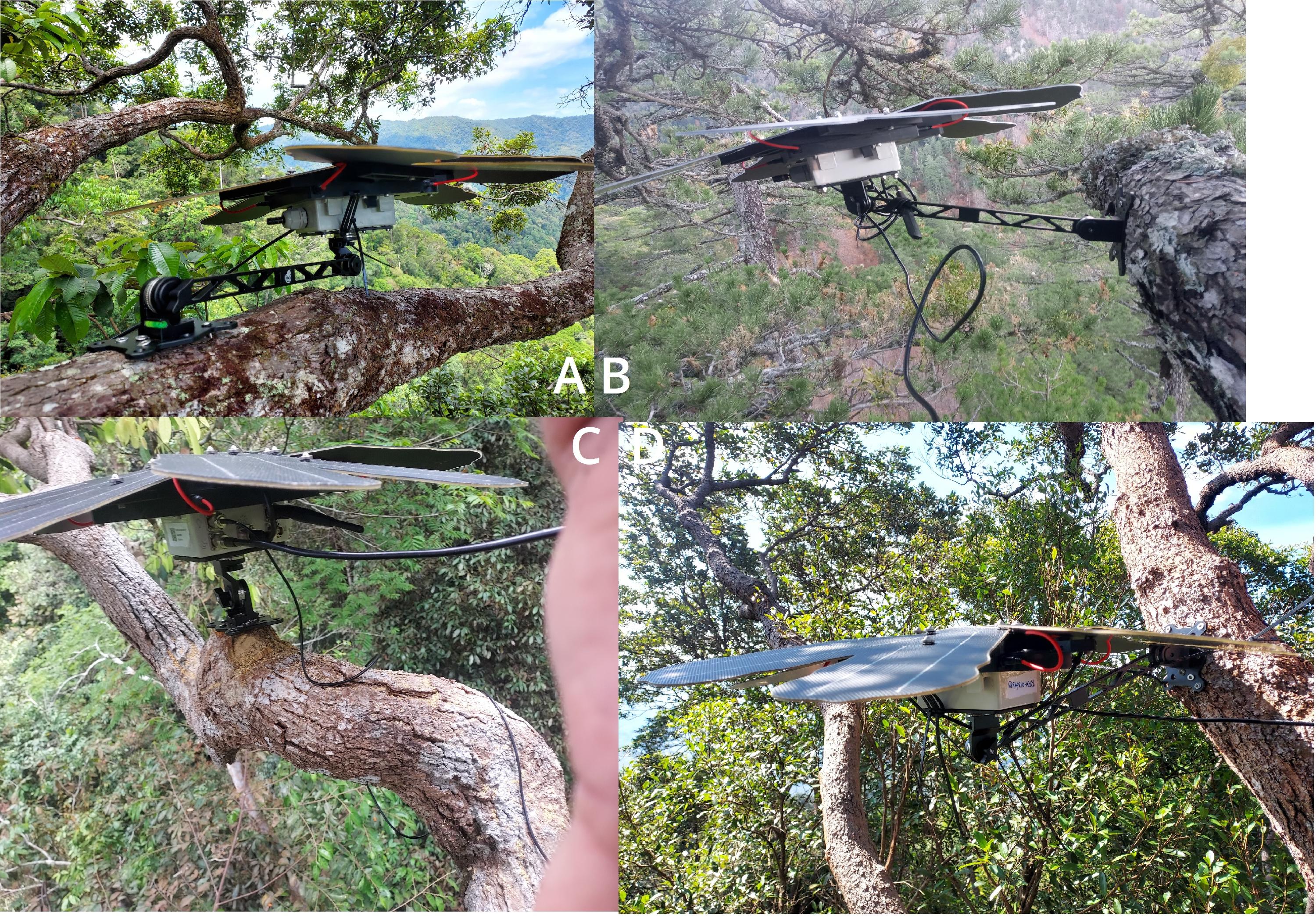
In Figure 9, positions A and B depict examples of less stable installations. A downward Arm (example D) is more secure than an upward Arm (example B). The Arm should not be necessary on a horizontal branch (example A) as direct attachment to the Baseplate (example C) is more secure.
If you attach the Box directly to the Baseplate then first remove the adaptor from the Arm and attach it directly to the Baseplate, as shown in Figure 11.
Step 5: Attaching Frame to Box
Once the Box is attached and secured to the Baseplate or Arm, the frame is the next vital part of the install.
However, before attaching the frame, you will need to TURN ON the device. In order to do this you will need to open the latch of the Guardian device. Locate the power switch and push it down to power on the device. Close the box an fasten the latch, being careful not to damage or catch any cables during closure.
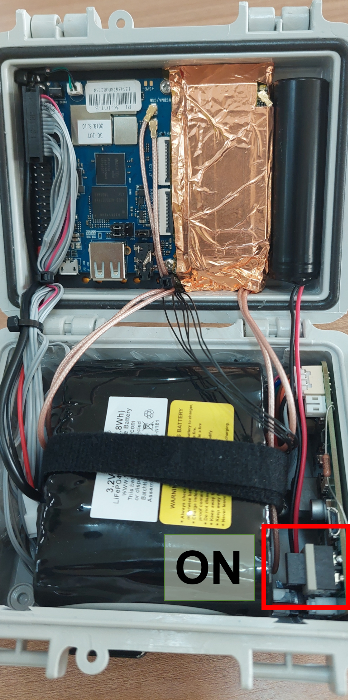
Turning on the Guardian in the tree must be done before attaching the frame.
The frame is the black propeller shaped cover that clips onto the Guardian box using the latch circled in the picture below (left). The latch must go over the side of Guardian box with the opening clips. The other side of the frame snuggly fits over the Guardian box and it is this side which must be put in the frame first then pulled down over the Guardian box by opening the latch. The frame must fit flat and level with overhanging rim of the Guardian box.

Moreover, as a further measure to secure the frame to Guardian box, you must attach the frame to the Guardian box plate by using at least 3 strong cable ties (which are capable of withstanding 100bs of force at least.). There are two rectangular attachment points, one on the frame and one on the Guardian box baseplate. These two rectangular points must be on the same side to be able to use the cable ties (Fig. 16).
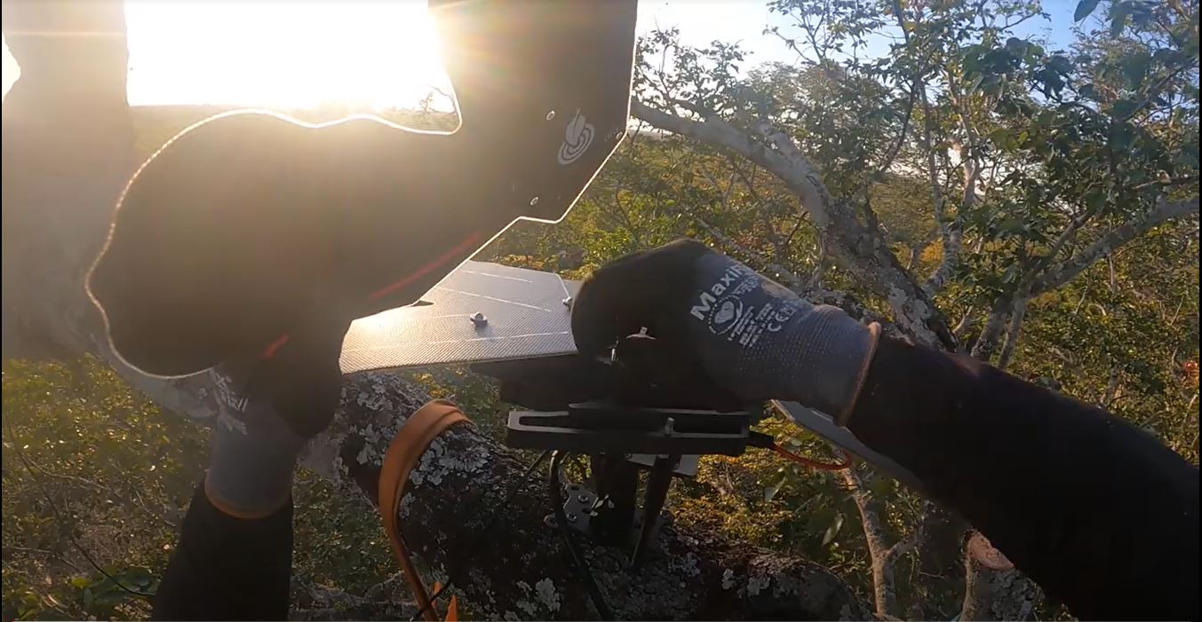
Step 6: Attaching Solar Panels to Frame
There are 4 panels per Guardian, the panels have 3 three holes in them which correspond to the screws on top of the frame (see pictures below). Once you have placed the Panels on the frame in the correct orientation, it is vital to put the flying saucer nuts back on the screws and tighten them up as much as possible to secure the panels.
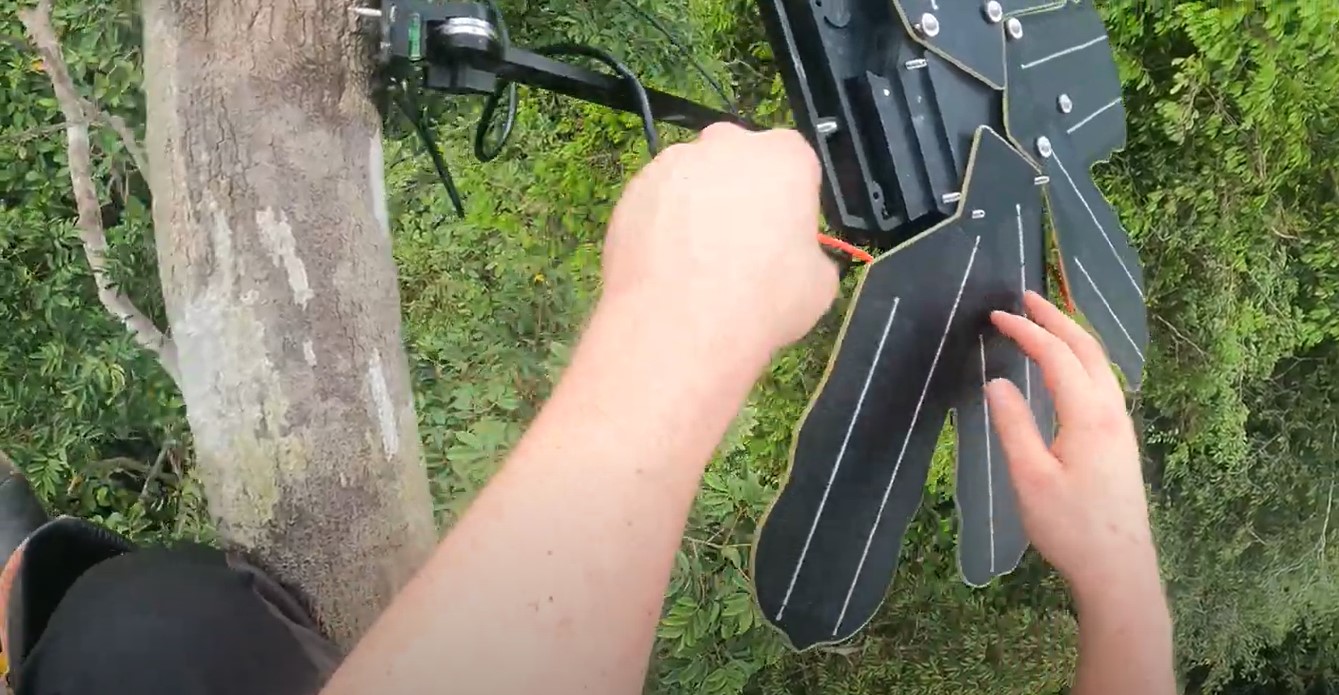
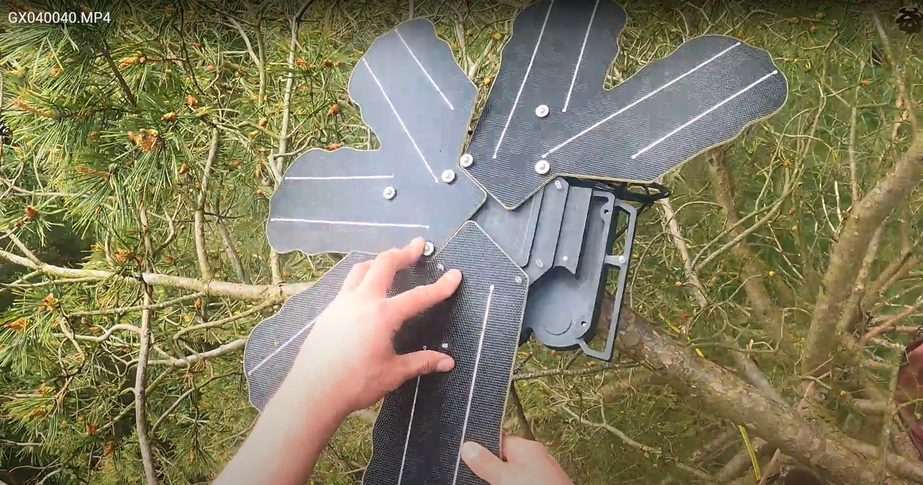

Moreover, each panel has a power cable which must be plugged into the frame. The cable needs to be pushed in fully into the frame until you hear a 'click'. Please see the images below of a fully connected cable.
It is vitally important to check that each individual solar panel is working. So before fully plugging in all four panels we can refer to Step 11.1 'Power Diagnostics' and open this checklist item. Then proceed to plug in each individual panel to ensure each panel creates power input.
If the results of the individual panel test show that one or more of the panels is not generating a charge, first make sure there is adequate sun. If there is clearly sun, then the panel or frame wiring is faulty. So abandon the install, return to the base and contact RFCx.
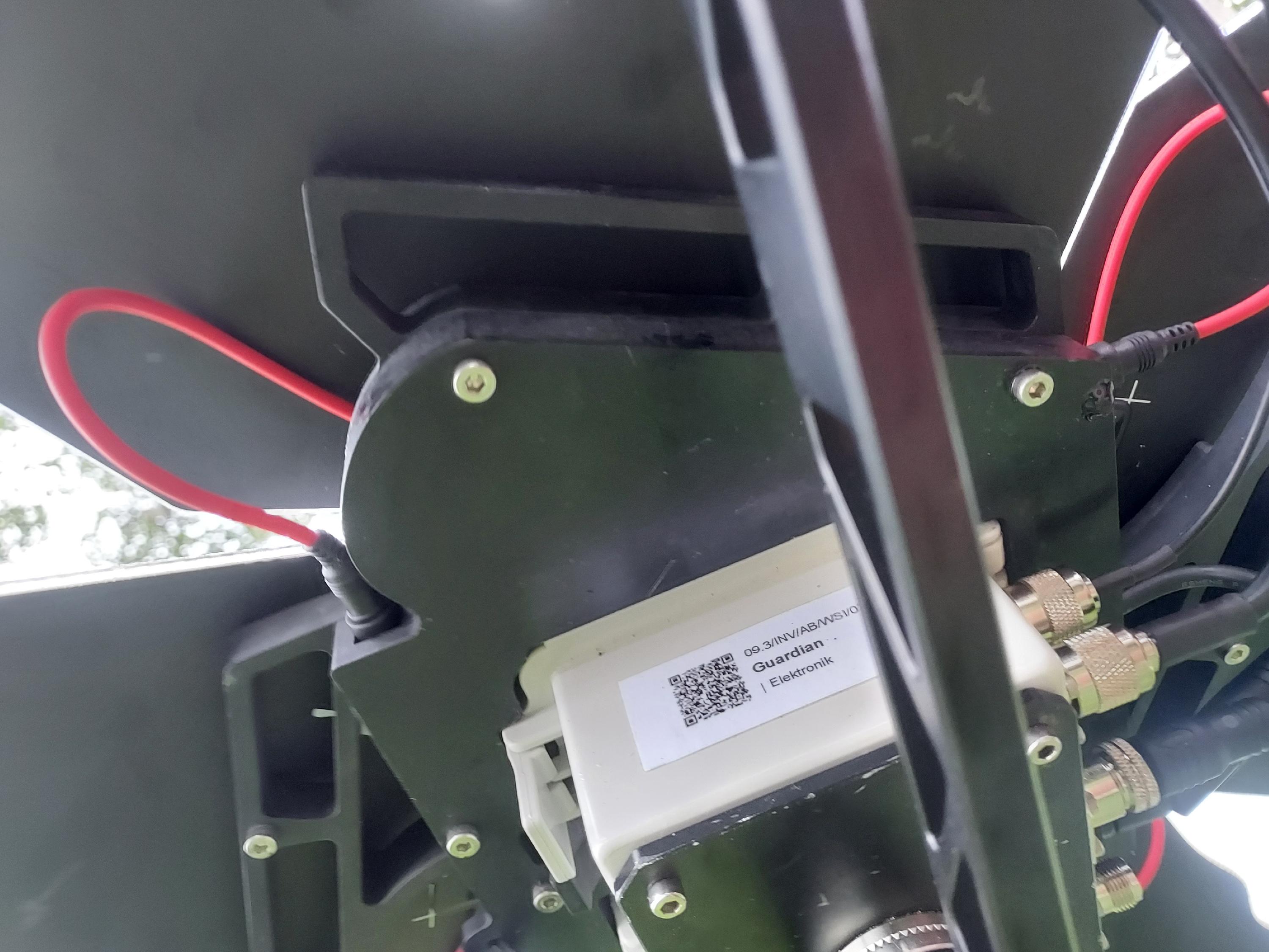
Step 7: Guardian Box Connections
There five connections on the Guardian box. Each one has a specific role and maybe or may not be necessary depending on the Guardian you are installing. The left picture below shows a GSM Guardian connection, while the right one shows a satellite Guardian.


Figure 19A and B - The attached WIFI antenna and power cables from the frame
Let's remind ourselves of the connections from top left to bottom right. Each connection corresponds to antenna type apart from the middle one which is the power cable. Each connection has a symbol which illustrates the function of the connection.
Top Left: GPS Antenna
Bottom Left: Satellite Antenna
Middle: Power Cable from Frame
Top Right: WiFi Antenna
Bottom Right: GSM Antenna
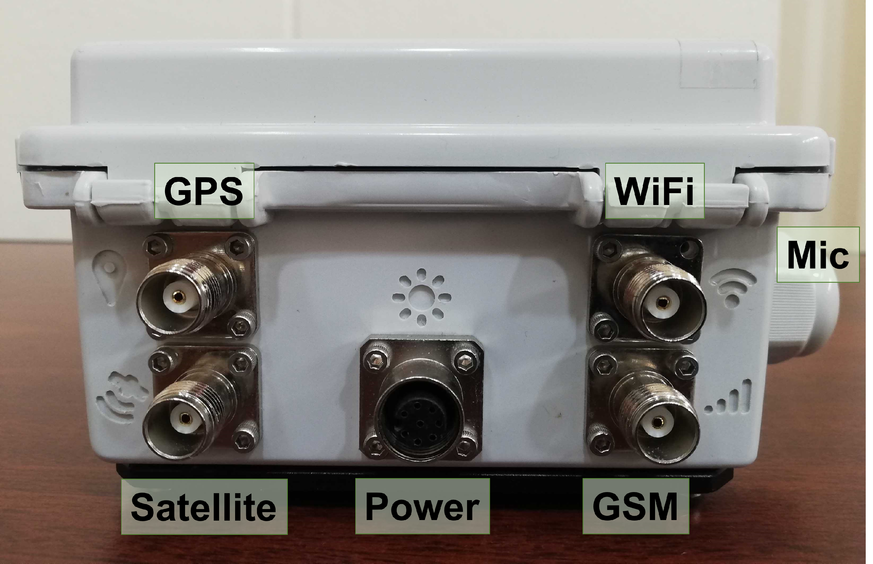
Both the WIFI Antennas and the Power Cables are essential for both types of Guardians (GSM and Satellite).
Step 8: Antenna Installations (Satellite Guardians)
WIFI and Power Cables
The WIFI Antenna is located in the RFCx case (below) and has a threaded screw which is used to tighten it to the top right connection on the guardian box.
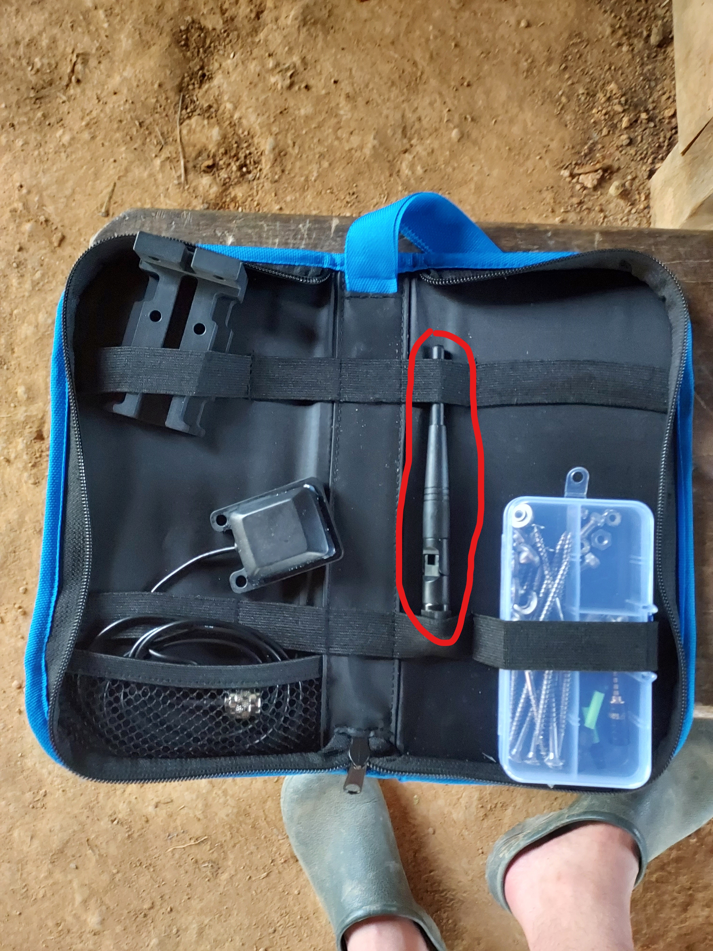
Figure 22A and B - The WIFI antenna in the Guardian case (A) and an installed Satellite Guardian with installed Antennas (B)
The black power cable which comes from the frame and is placed in the middle connection. The power cable has specific orientation so please rotate the cable around until it fits, then tighten the safety latch to it doesn't come undone.
Satellite Guardians - THIS STEP IS ONLY FOR SATELLITE GUARDIANS. FOR GSM GUARDIANS SKIP TO STEP 9
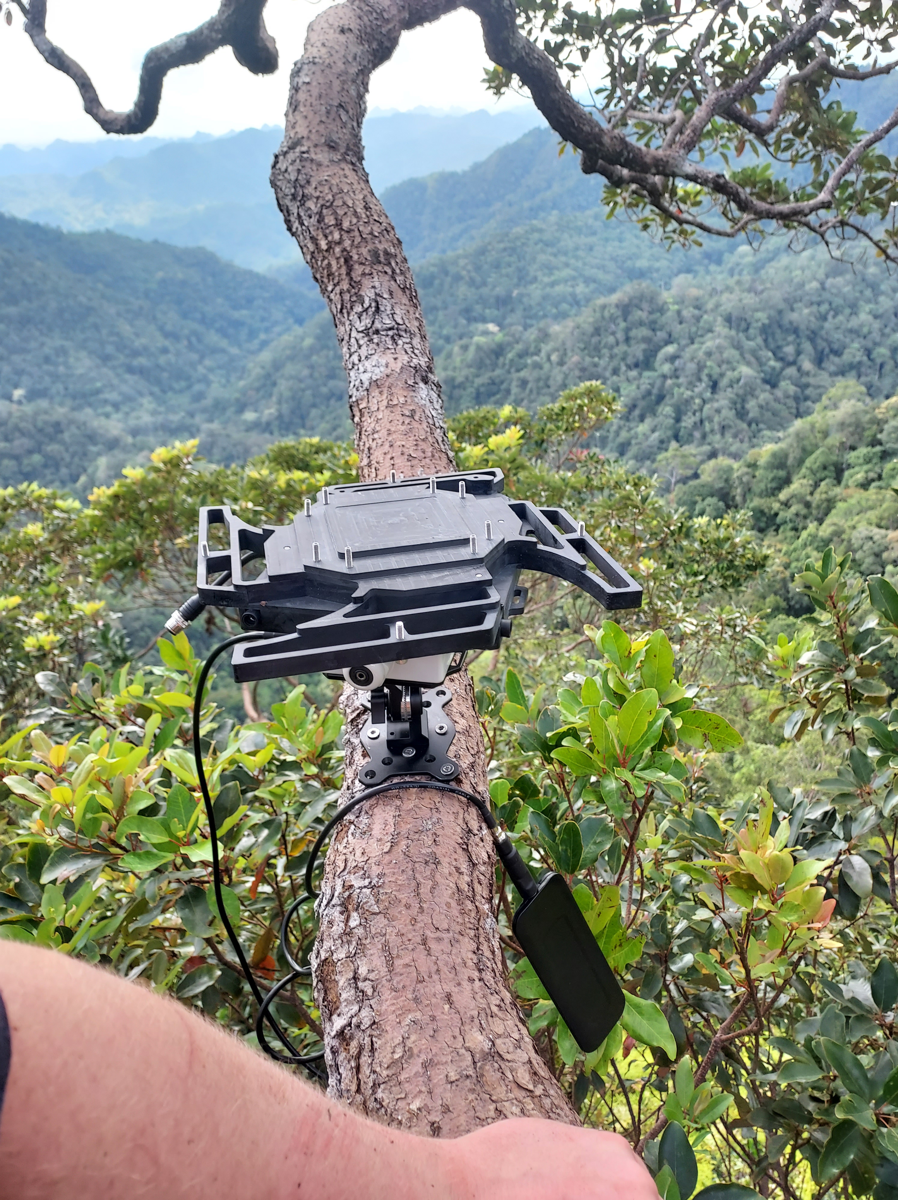
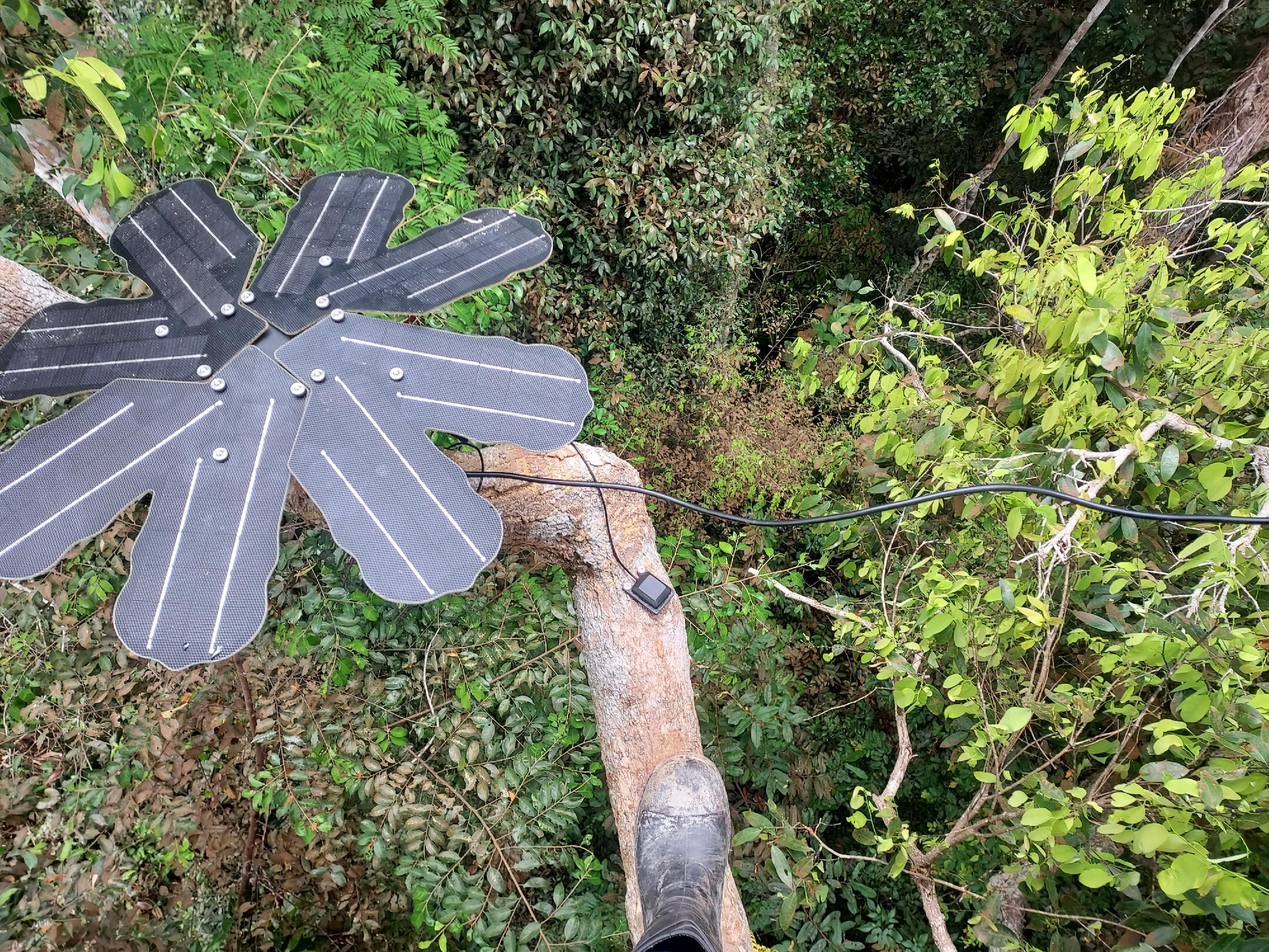
For Satellite Guardians, they require the Satellite Antenna to be installed far away from the Guardian Box using the full length of the antenna cable
GPS Antenna - the GPS antenna has a short cable and should be placed close to the full Guardian device. The GPS Antenna needs to screwed into the tree using the two holes on the mount. While the connection end should be placed on the GPS antenna connection (Fig 23).
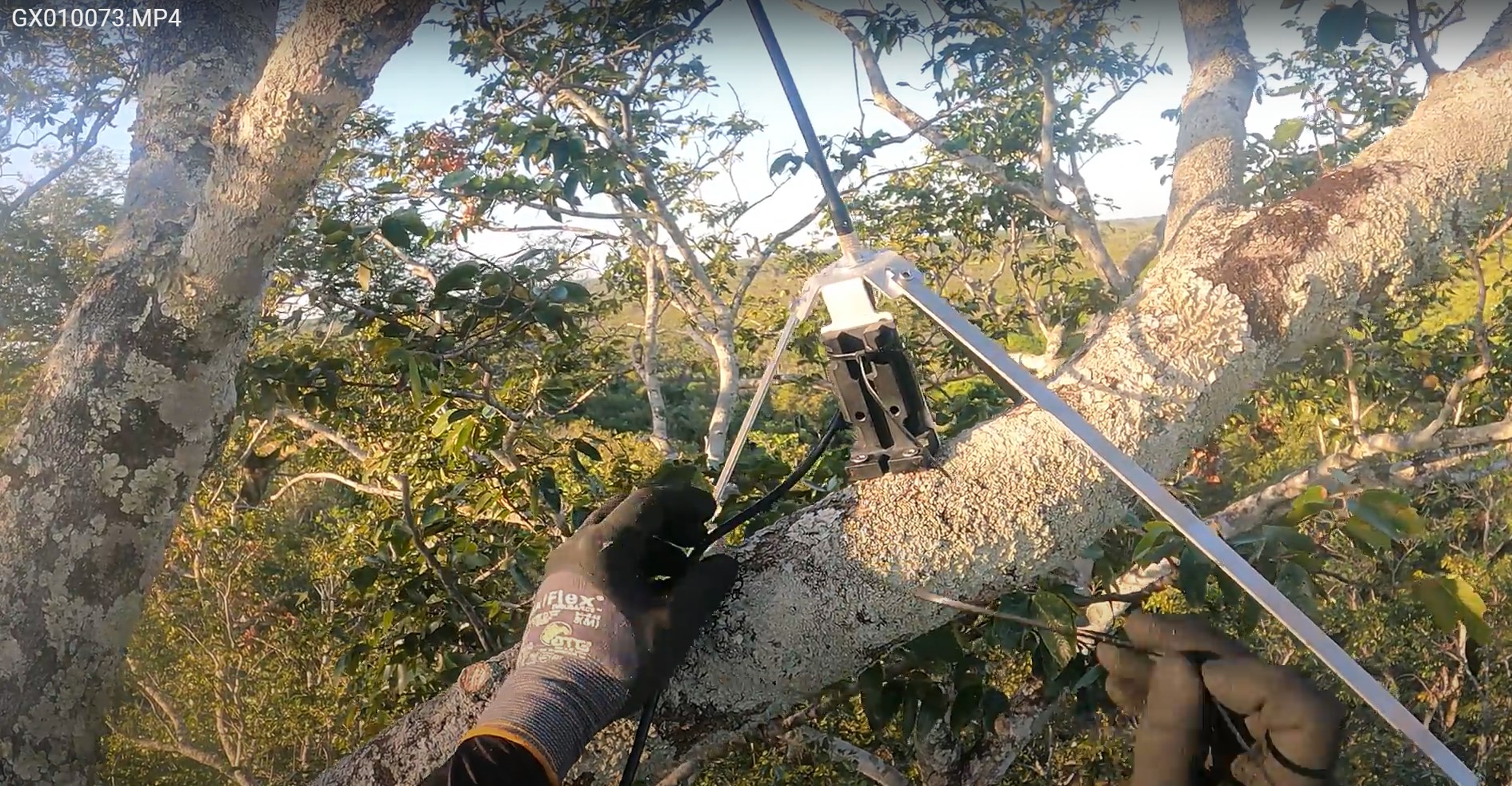
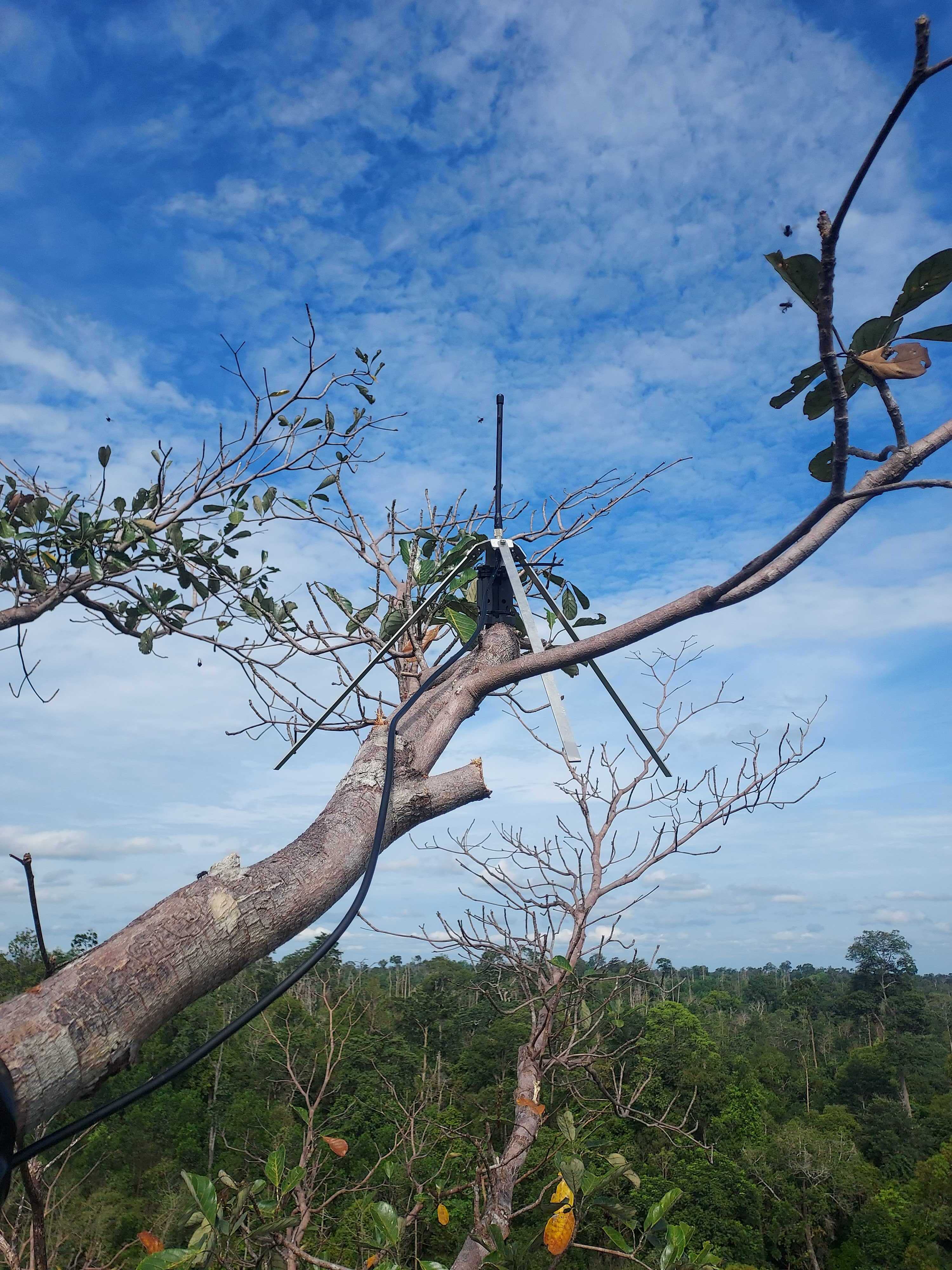
Satellite Antenna - In order to install the Satellite Antenna you must firstly install the mount on a part of the tree which has a flat surface and has no to very little canopy cover blocking communication between the Satellite Guardian and the Satellite.
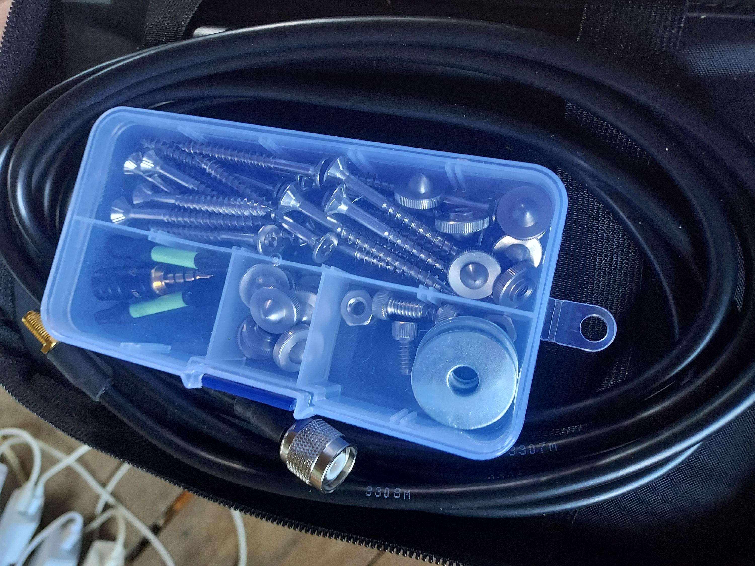
The Antenna is made up of bracket, three radials (long metal 'legs'), three nuts & bolts, two metal washers, the actual antenna and the cable. (Please see the Satellite Antenna guide here).
The Satellite Antenna Must be Installed higher in the tree than the main Guardian Device.
The mount must be first screwed to the tree, then the bracket with the antenna and cable will be zip tied to the mount using three zip ties. The then the radials should be attached to the bracket.
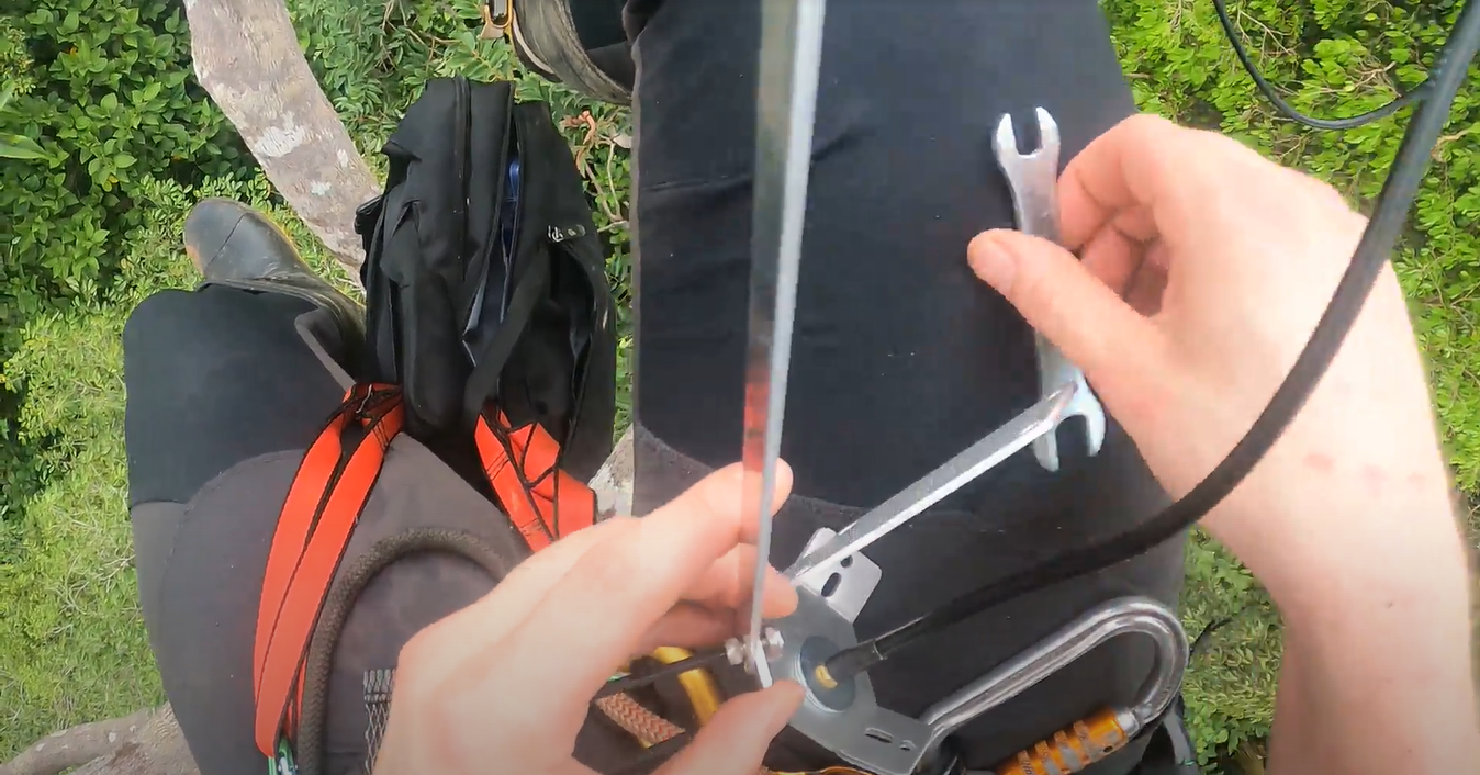
The Satellite Antenna radials must be attached to the bracket in the tree using a 8mm spanner and 4m Alan key (Fig 24). You can assemble the satellite antenna on the ground when
It is prudent to familiarise oneself with the satellite antenna install before climbing and installing in a tree. We have pre-installation set-up guide that you should follow before installing i an tree.
Step 9 - Antenna Installations (GSM Guardians)
GSM Guardians - THIS STEP IS ONLY FOR GSM GUARDIANS, FOR SATELLITE GUARDIANS RETURN TO STEP 8
The GSM antenna fits into the mount grooves and the antenna is then zip tied to the mount securely. The mount should be then screwed to tree using the holes.
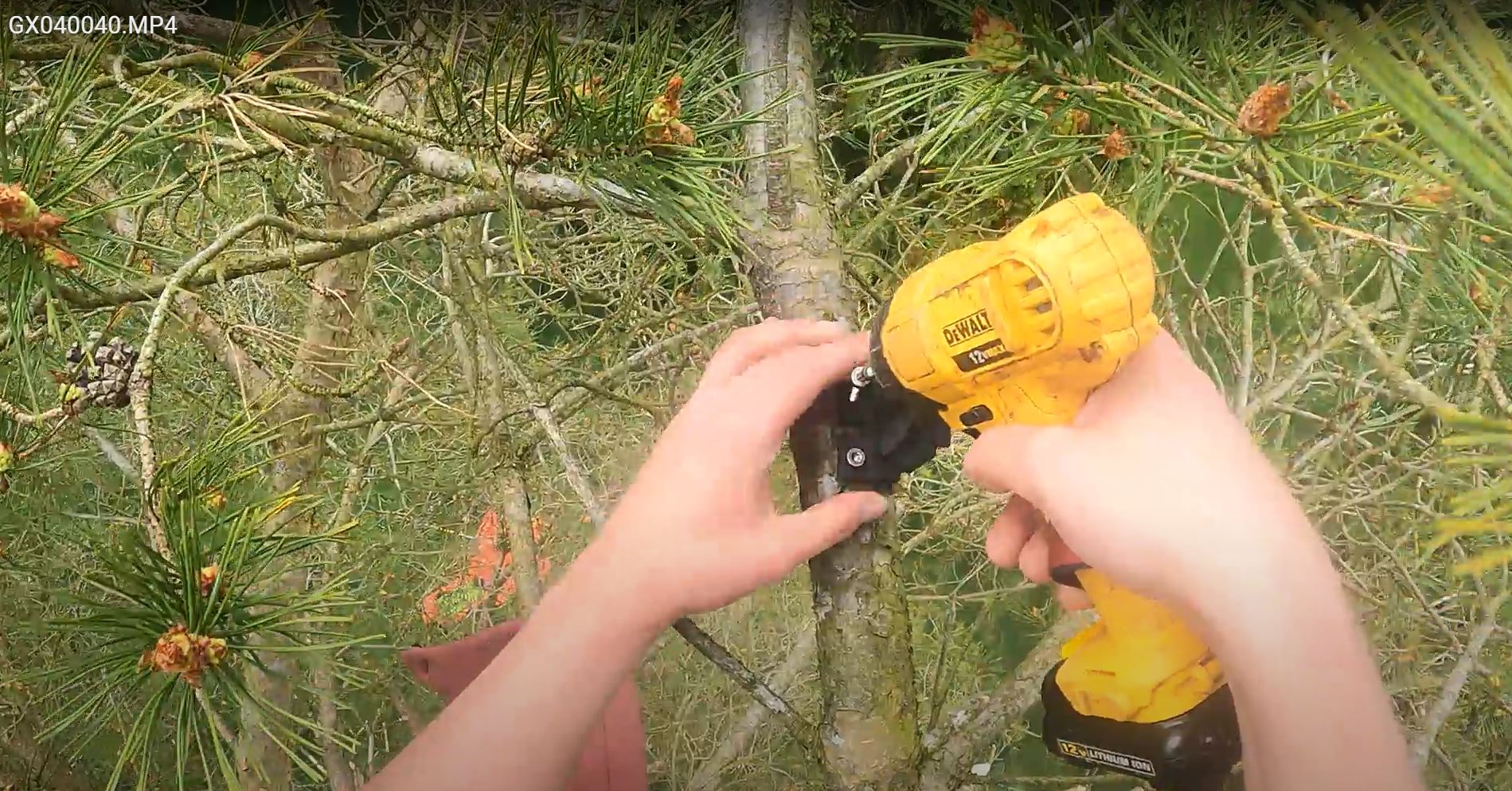
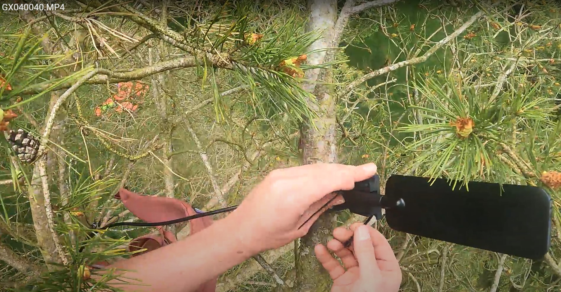

Figure 32 - GSM antenna attached to the tree above the Guardian
Step 10: Microphone and Mic cover attachment
The microphone must not be forgotten as a step, otherwise the Guardian will no record anything! The microphone is inserted in the hexagonal mount on Guardian box (Fig 34) until you hear a 'click'. Then the foam microphone cover should be placed over the microphone to buffer against strong winds (Fig 35). This cover should be zip tied and tighten around the hexagonal mount.

Figure 34 - The Microphone attached to the Guardian box

Figure 35 - The microphone cover zip tied over the microphone.
Step 11: Guardian App Checks (For GSM and Satellite Guardians)
Firstly, open the Guardian app and you will see a map of your location with a big green plus button at the bottom. Select the green plus button and chose Guardian.
On the Guardian App, check that you can see and connect to the device.
Open the Guardian App on your Android phone and click on connect to guardian on deployment screen. Select the Guardian you and press 'connect'. Then you will see the Guardian set up Checklist. If you do not see the Guardian appear when initially searching then you have forgotten to turn it on. If the Guardian is turned 'on' then it may be ill functioning and shouldn't be installed.
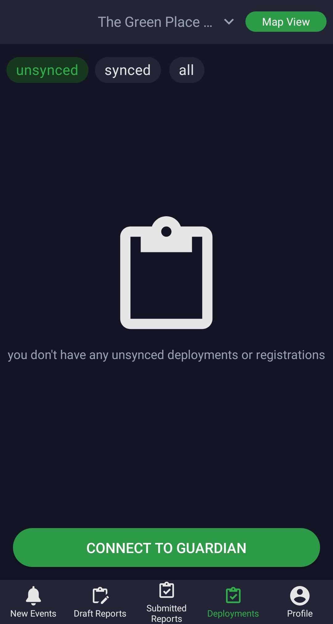

Figure 37 - Choosing the Guardian to Connect to

Figure 38 - The Companion app Guardian Checklist
Step 11.1 Power Checks
Select "Power Diagnostics" on the checklist.
Fig 39 shows the companion app before panels are attached.

Figure 39 - Companion app not detecting any power input

Figure 40 - The Guardian successfully charging through the solar panels.

Figure 41 - The companion app dynamic charging graph showing variable levels of charging.
In order to properly test the Guardians ability to charge you need to connect each panel one by one to the frame and see the response on the companion.
Once the individual panel check has been done you should check that all 4 solar panels are plugged in fully.
You should see a voltage of at least 6000mV, when all 4 panels are connected and charging. This will create a power surplus which is vital for making up for the power lost over night.
Step 11.2 Satellite Guardian Connectivity
Fig 42 shows how the Companion App connects to the Satellite Guardian.
In order for the Satellite Guardian to function, connect and send data it will need to detect the Satellite Module and give a swarm ID as well as detect the GPS antenna and the correct time and date of the time zone you're in.

Figure 43 - Satellite Communication Configuration
For Satellite Guardians, select 'Satellite only' and then 'auto'. This ensures the swarm tile switches when needed (as swarm satellite passes).
As long as you have the correct project selected the satellite pass times will be preprogramed.
Step 11.3 Background noise check for Satellite Guardians
Satellite Guardians - THIS STEP IS ONLY FOR SATELLITE GUARDIANS. FOR GSM GUARDIANS SKIP TO STEP 11.5
Figure 41 and 42 show background noise from a Satellite Guardian. The Companion App has a ledger which illustrates what constitutes good or bad background noise. The companion measures background noise in dBm, the number will appear as a negative number. As a general rule, the further away the number is from Zero, the lower the background noise.
< 93 is 'bad' this mean the Guardian may struggle to communicate with the satellite during pass times
93 - 97 is 'OK' or acceptable for communication
97 - 100 is pretty good for communication
> 104 is ideal for communication
The harder it is for the Guardian to communicate, the more battery it will use. Moreover, the satellite pass times last 2-3 hours, so if the Guardian is struggle to communicate, it may miss the pass time entirely.
Remember, in order to ensure background noise is as low as possible, ensure the Satellite Antenna is a far away from the Guardian box as possible. As well, the Antenna should be above the Guardian box.

Figure 44 - Background noise level that would interfere with satellite communication

Figure 45 - Background noise levels that allow satellite communication
Step 11.4 GSM Signal Strength for GSM Guardians
GSM Guardians - THIS STEP IS ONLY FOR GSM GUARDIANS, FOR SATELLITE GUARDIANS RETURN TO STEP 11.5
For GSM Guardians the companion app will show different information (figures 43 and 44). The Companion App must detect the SIM card and detect the Guardians local time. Seen by the 'green tick' that corresponds to it. If a red cross appears, then the Guardian isn't able to detect the SIM and therefore won't connect or send data.

Figure 46 - Configuring Communication for GSM Guardians

Figure 47 - Display of GSM Signal Strength for GSM Guardians
Figure 47 shows a Guardian connected to GSM signal, with a signal strength of -57 dBm. The GSM Guardian signal strength is the inverse of the satellite Guardians. Meaning, -57 dBm is very good signal strength for a GSM Guardian, while it would be extremely bad for a satellite guardian.
As a general rule, the GSM signal strength should be no further from zero than -91 dBm. Meaning, -97 to -104 dBm would mean a GSM guardian would struggle to send data and therefore consume more battery.
Step 11.5 Audio Parameter Configuration
At this step, you can select file format, Sample rate, Bitrate, Recording duration, Cycle(s) skipped between recordings and schedule recording time as you expect the device to be recording the audios.

Step 11.6 Microphone Check
Open the Microphone Capture Test step. Press "Begin".

Your phone should start playing the audio streamed from the Guardian device, and a spectrogram is generated on the screen.

If there is no audio played then:
- Check the microphone is inserted fully
If the audio is unclear or distorted then:
- Ensure that the microphone is pointing away from the tree trunk as this can cause an echo
Step 11.7 Set Site Location
-
Choose the site

Figure 51 - Creating a name for the site
- If the site was created in advance then type the name to search for it and select it
- Otherwise type the new site name and select create
-
Update the site coordinates

Figure 52 - Setting the Guardian's location
- Take screenshot of site location info for records
- Press the highlighted re-centre button (figure 48) to ensure the location is correct
- Check the map to ensure you're in the right place
- Set the location


Step 11.8 Add Photos and complete deployment
Photos are integral to the installation. They act as proof of a successfully installed Guardian that we can come back to learn lessons of potential failures. Moreover, it acts as proof of a successful install.
*RFCx may ask the installer to return to a deployed Guardian to correct an issue*
Take photos of the finished installation. The photos must cover the steps covered in this guide i.e. the baseplate and arm angle, the securely cable tied frame, the position of the solar panels, the position of the Antennas (GSM or Satellite) in relation to the Guardian Box. Also, the photos must clearly show the position of the Guardian in relation to access to sunlight and its location on the tree (i.e. is it at the top).

Figure 53 - Adding photos to the deployment as proof of install
We recommend you add photos from your gallery, that you have already taken. As this way the photos are saved to your phone and can be send directly to the WhatsApp group for verification. Otherwise, the photos from 'Take Photo' option will not be saved to your phone and will be sent to Arbimon when synced.
Deploy Guardian using the Companion App

Figure 54 - Button to deploy the companion app
Once the Guardian is deployed you are ready for the final checks
Step 10: Final checks
- Ensure brackets, frame and antennas are secure.
- Zip-tie the base of the Guardian device with the the solar panel frame.
- If in a windy location, secure the Guardian to the tree branch with paracord or large zip ties.

Figure 55 - Final security on an installed Guardian (para cord tying to tree)
Safely return to ground level.
Pull over a length of paracord when pulling ropes over so you can easily we climb the tree.
Step 12: Sync deployment
Return to a place where you connect with cell signal or WIFI. Please ensure that all deployments are synced. The deployments usually get synced automatically.
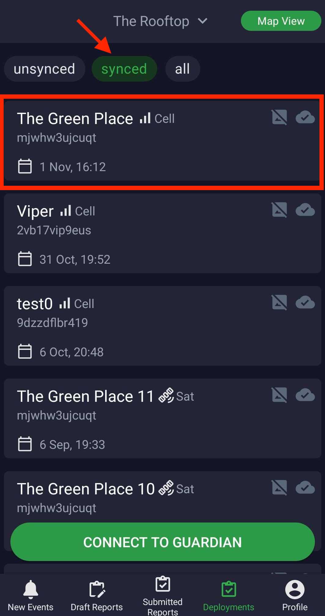
You will know a deployment is synced as you will receive an email telling the Guardian has been deployed as well, You can see the synced deployment in the synced tab and no marker in Map View button.
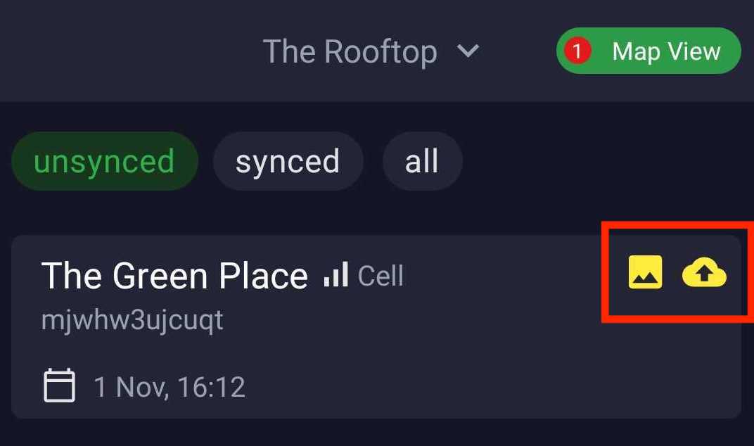
You also can check if there are any unsynced deployments by opening the Guardian app. Then go to deployment screen and you can see unsynced deployments. Press unsynced tab, you will see all unsynced works.
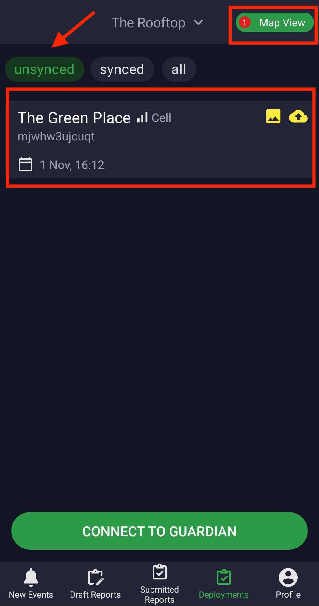
To sync deployments manually, go to unsynced tab and press on the yellow icons (photo icon and upload icon) in the deployment, so that you do not have to wait for syncing system. After the deployment synced the icons will change to grey color and the deployment will disappear from unsynced tab.